CIRCUIT DIAGRAM & CIRCUIT SYMBOLS
This article has focused on the key ingredients of an electric
circuit and upon the concepts of electric potential difference, current and
resistance. Conceptual meaning of terms have been introduced and applied to simple
circuits. Mathematical relationships between electrical quantities have been
discussed and their use in solving problems has been modeled. Lesson 4 will
focus on the means by which two or more electrical devices can be connected to
form an electric circuit. Our discussion will progress from simple circuits to
mildly complex circuits.
Electric
circuits, whether simple or complex, can be described in a variety of ways. An
electric circuit is commonly described with mere words. Saying something like
"A light bulb is connected to a D-cell" is a sufficient amount of
words to describe a simple circuit. On many occasions in Lessons 1 through 3,
words have been used to describe simple circuits. Upon hearing (or reading) the
words, a person grows accustomed to quickly picturing the circuit in their
mind. But another means of describing a circuit is to simply draw it.
Describing Circuits with Words
"A circuit contains a light bulb and a 1.5-Volt D-cell."
\
|
Describing Circuits with Drawings
|
Two types of connections :
1. Series Connection
2. Parallel Connection
Equivalent Resistance and Current :
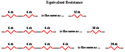
Charge flows together through the external circuit at a rate that is everywhere the same. The current is no greater at one location as it is at another location. The actual amount of current varies inversely with the amount of overall resistance. There is a clear relationship between the resistance of the individual resistors and the overall resistance of the collection of resistors. As far as the battery that is pumping the charge is concerned, the presence of two 6-Ω ;resistors in series would be equivalent to having one 12-Ω resistor in the circuit. The presence of three 6-Ω resistors in series would be equivalent to having one 18-Ω resistor in the circuit. And the presence of four 6-Ω resistors in series would be equivalent to having one 24-Ω resistor in the circuit.

This is the concept of equivalent resistance. The equivalent resistance of a circuit is the amount of resistance that a single resistor would need in order to equal the overall effect of the collection of resistors that are present in the circuit. For series circuits, the mathematical formula for computing the equivalent resistance (Req) is
where R1, R2, and R3 are the resistance values of the individual resistors that are connected in series.
Equivalent Resistance :
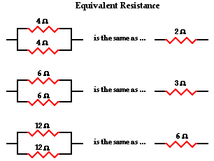
The actual amount of current always varies inversely with the amount of overall resistance. There is a clear relationship between the resistance of the individual resistors and the overall resistance of the collection of resistors. To explore this relationship, let's begin with the simplest case of two resistors placed in parallel branches, each having the same resistance value of 4 Ω. Since the circuit offers two equal pathways for charge flow, only one-half the charge will choose to pass through a given branch. While each individual branch offers 4 Ω of resistance to any charge that flows through it, only one-half of all the charge flowing through the circuit will encounter the 4 Ω resistance of that individual branch. Thus, as far as the battery that is pumping the charge is concerned, the presence of two 4-Ω resistors in parallel would be equivalent to having one 2-Ω resistor in the circuit. In the same manner, the presence of two 6-Ω resistors in parallel would be equivalent to having one 3-Ω resistor in the circuit. And the presence of two 12-Ω resistors in parallel would be equivalent to having one 6-Ω resistor in the circuit.

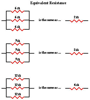
Now let's consider another simple case of having three resistors in parallel, each having the same resistance of 6 Ω. With three equal pathways for charge to flow through the external circuit, only one-third the charge will choose to pass through a given branch. Each individual branch offers 6 Ω of resistance to the charge that passes through it. However, the fact that only one-third of the charge passes through a particular branch means that the overall resistance of the circuit is 2 Ω. As far as the battery that is pumping the charge is concerned, the presence of three 6-Ω resistors in parallel would be equivalent to having one 2-Ω resistor in the circuit. In the same manner, the presence of three 9-Ω resistors in parallel would be equivalent to having one 3-Ω resistor in the circuit. And the presence of three 12-Ω resistors in parallel would be equivalent to having one 4-Ω resistor in the circuit.

This is the concept of equivalent resistance. The equivalent resistance of a circuit is the amount of resistance that a single resistor would need in order to equal the overall effect of the collection of resistors that are present in the circuit. For parallel circuits, the mathematical formula for computing the equivalent resistance (Req) is
where R1, R2, and R3 are the resistance values of the individual resistors that are connected in parallel. The examples above could be considered simple cases in which all the pathways offer the same amount of resistance to an individual charge that passes through it. The simple cases above were done without the use of the equation. Yet the equation fits both the simple cases where branch resistors have the same resistance values and the more difficult cases where branch resistors have different resistance values. For instance, consider the application of the equation to the one simple and one difficult case below.
 |
1/Req = 1/(12 Ω) + 1/(12 Ω) + 1/(12 Ω)
Using a calculator ...
1/Req = 0.25 Ω-1
Req = 1 / (0.25 Ω-1)
Req = 4.0 Ω
|
 |
1/Req = 1/(5.0 Ω) + 1/(7.0 Ω) + 1/(12 Ω)
Using a calculator ...
1/Req = 0.42619 Ω-1
Req = 1 / (0.42619 Ω-1)
Req = 2.3 Ω
|


0 Comments:
Post a Comment